 Toyota Camry XV30 (2002–2006) Service ManualEngine mechanical
Cylinder block assy (2AZ−FE)(From July, 2003)
Cylinder block assy (2AZ−FE)(From July, 2003)
COMPONENTS
OVERHAUL
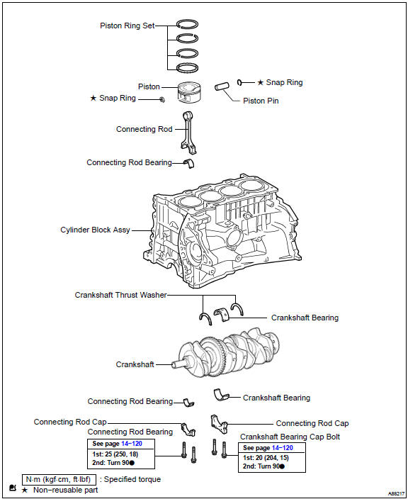
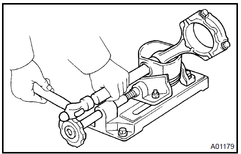
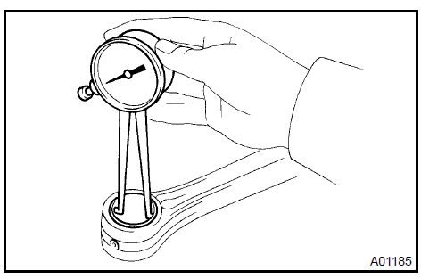
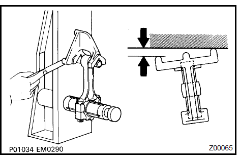
1. INSPECT CONNECTING ROD THRUST CLEARANCE
a. Using a dial indicator, measure the thrust clearance while moving the connecting rod back and forth.
Specified thrust clearance: 0.160 to 0.362 mm (0.0063 to 0.0143 in.)
If the thrust clearance is greater than the maximum, replace the connecting rod assemblys.. If necessary, replace the crankshaft.
Inspect connecting rod thrust clearance
2. INSPECT CONNECTING ROD OIL CLEARANCE
HINT: The connecting rod cap bolts are tightened in 2 progressive steps.
a. Check that the matchmarks on the connecting rod and cap are aligned to ensure the correct reassembly.
HINT: The matchmarks on the connecting rods and caps are for ensuring the correct reassembly.
-
Remove the 2 connecting rod cap bolts.
-
Using the 2 removed connecting rod cap bolts, remove the connecting rod cap and lower bearing by wiggling the connecting rod cap right and left.
HINT: Keep the lower bearing inserted to the connecting rod cap.
-
Clean the crank pin and bearing.
-
Check the crank pin and bearing for pitting and scratches
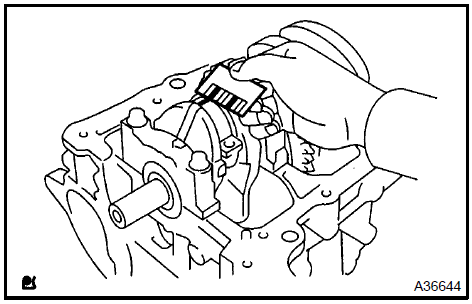
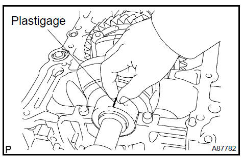
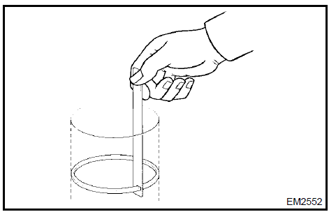
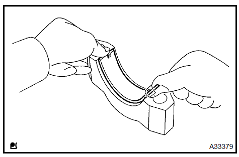
f. Lay a strip of Plastigage on the crank pin.
-
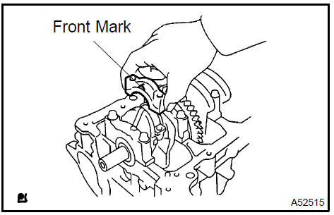
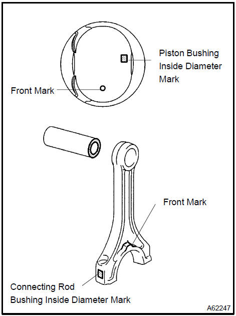
Check that the front mark of the connecting rod cap is facing in the correct direction.
-
Apply a light coat of engine oil on the threads and under the heads of the connecting rod cap bolts.
-
Install the connecting cap (see step 37).
NOTICE: Do not turn the crankshaft.
j. Remove the 2 bolts and connecting rod cap.
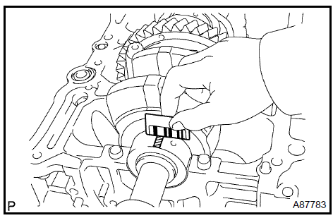
k. Measure the Plastigage at its widest point.
Specified oil clearance: 0.024 to 0.080 mm (0.0009 to 0.0031 in.)
If the crank pin or bearing is damaged, replace the bearings. If necessary, replace the crankshaft.
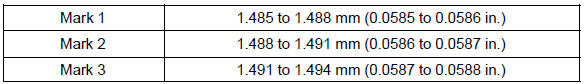
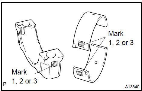
HINT: If replacing a bearing, replace it with one that has the same number as the connecting rod. There are 3 sizes of standard bearings: 1, 2 and 3.
Standard bearing center wall thickness:
l. Completely remove the Plastigage.
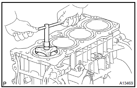
3. REMOVE PISTON SUB−ASSY W/CONNECTING ROD
-
Using a ridge reamer, remove all the carbon from the top of the cylinder.
-
Push the piston, connecting rod assembly and upper bearing through the top of the cylinder block.
HINT:
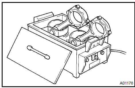
-
Keep the bearing, connecting rod and cap together.
-
Arrange the piston and connecting rod assemblies in the correct order.
Remove piston sub-assy w/connecting rod
-
REMOVE CONNECTING ROD BEARING
-
REMOVE PISTON RING SET
-
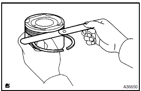
Using a piston ring expander, remove the 2 compression rings.
-
Remove the 2 side rails and oil ring by hand.
Remove piston ring set
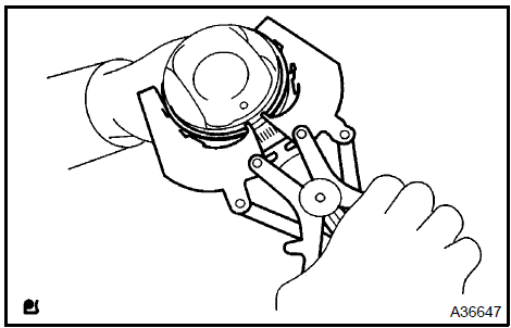
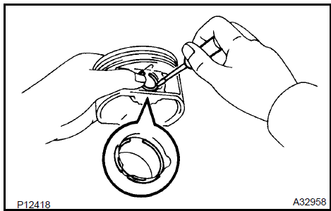
6. REMOVE PISTON PIN HOLE SNAP RING
a. Using a small screwdriver, pry out the 2 snap rings.
Remove piston pin hole snap ring
7. REMOVE PISTON
a. Gradually heat the piston to approxinately 80 to 90 C (176 to 194 F).
b. Using a plastic−faced hammer and brass bar, lightly tap out the piston pin and remove the connecting rod.
HINT:
-
The piston and pin are a matched set.
-
nge the pistons, pins, rings, connecting rods and bearings in the correct order.
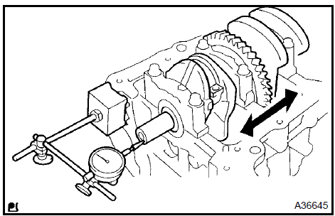
8. INSPECT CRANKSHAFT THRUST CLEARANCE
a. Using a dial indicator, measure the thrust clearance while prying the crankshaft back and forth with a screwdriver.
Specified thrust clearance: 0.040 to 0.300 mm (0.0016 to 0.0118 in.)
If the thrust clearance is greater than the maximum, replace the thrust washers as a set.
Thrust washer thickness: 1.930 to 1.980 mm (0.0760 to 0.0780 in.)
Inspect crankshaft thrust clearance
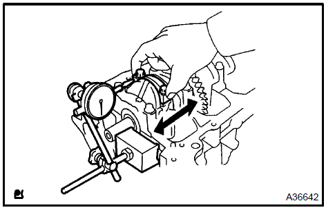
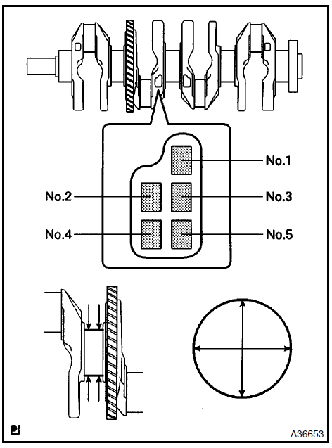
9. INSPECT CRANKSHAFT OIL CLEARANCE
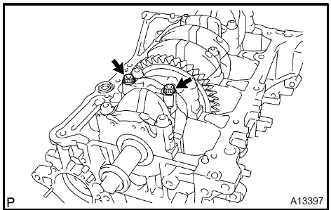
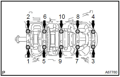
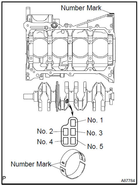
a. Uniformly loosen and remove the 10 main bearing cap bolts, in the sequence shown in the illustration.
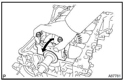
b. Use 2 removed main bearing cap bolts to remove the 5 main bearing caps and 5 lower bearings.
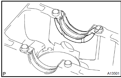
NOTICE: Insert the bolts into one of the caps. Ease the cap out by gently pulling up and applying force toward the front and back side of the cylinder block, as shown in the illustration.
Take care not to damage the contact surfaces of the cap and cylinder block.
HINT:
-
Keep the lower bearing and main bearing cap together.
-
Arrange the main bearing caps in correct order.
c. Lift out the crankshaft.
HINT: Keep the upper bearings together with the cylinder block.
-
Clean each main journal and bearing.
-
Check each main journal and bearing for pitting and scratches.
If the journal or bearing is damaged, replace the bearings.
If necessary, replace the crankshaft.
-
Place the crankshaft on the cylinder block.
-
Lay a strip of Plastigage across each journal.
-
Install the main bearing caps (see step 36).
HINT: Do not turn the crankshaft.
i. Remove the main bearing cap (see steps a. and b. above).
j. Measure the Plastigage at its widest point.
Standard oil clearance: 0.008 to 0.024 mm (0.00031 to 0.00094 in.)
If the oil clearance is greater than the maximum, replace the bearings. If necessary, replace the crankshaft.
k. If using a standard bearing, replace it with one having the same number. If the number of the bearing cannot be determined, select the correct bearing by adding together the numbers imprinted on the cylinder block and crankshaft, and then selecting the bearing according to the chart below. There are 4 sizes of standard bearings: 1, 2, 3, and 4.
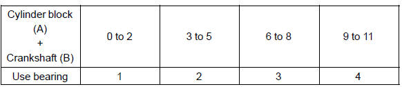
HINT:
EXAMPLE
Cylinder block 4 a. + Crankshaft 3 b. =
Total number 7 (Use bearing 3)
Reference:
l. Completely remove the Plastigage.
10. REMOVE CRANKSHAFT
-
Lift out the crankshaft.
-
Remove the 5 upper main bearings and 2 thrust washers from the cylinder block.
HINT: Arrange the main bearings and thrust washers in the correct order.
-
REMOVE CRANKSHAFT THRUST WASHER UPPER
-
REMOVE CRANKSHAFT BEARING
HINT: Arrange the bearings in the correct order.
13. REMOVE CRANKSHAFT BEARING No.2
HINT: Arrange the bearings in the correct order.
-
REMOVE STUD BOLT
-
CLEAN CYLINDER BLOCK SUB−ASSY
NOTICE: If the cylinder is washed at high temperatures, the cylinder liner sticks out beyond the cylinder block.
Always wash the cylinder block at a temperature of 45 C (113 F) or less.
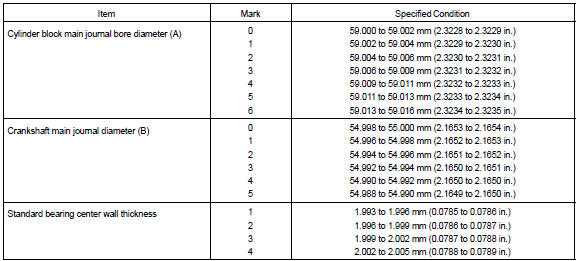
16. INSPECT CYLINDER BLOCK FOR FLATNESS
a. Using a precision straight edge and feeler gauge, measure the surface contacting the cylinder head gasket for warpage.
Maximum warpage: 0.05 mm (0.0020 in.)
If the warpage is greater than the maximum, replace the cylinder block.
Inspect cylinder block for flatness
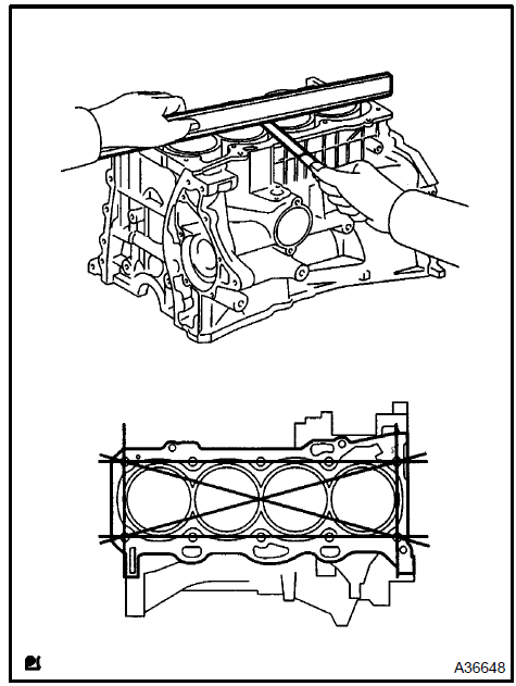
17. INSPECT CYLINDER BORE
a. Using a cylinder gauge, measure the cylinder bore diameter at positions A and B in the thrust and axial directions.
Standard diameter: 88.500 to 88.633 mm (3.4843 to 3.4894 in.)
If the average of the measured diameters is greater than the maximum, replace the cylinder block.
Inspect cylinder bore
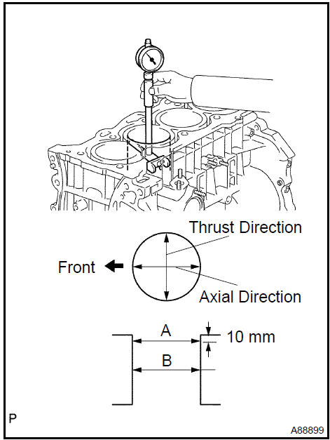
18. INSPECT PISTON DIAMETER
a. Using a micrometer, measure the piston diameter at right angles to the piston pin center line, 30.3 mm (1.193 in.) from the piston head.
Piston diameter: 88.439 to 88.449 mm (3.4818 to 3.4822 in.)
Inspect piston diameter
19. INSPECT PISTON CLEARANCE
a. Subtract the piston diameter measurement from the cylinder bore diameter measurement.
Specified oil clearance: 0.051 to 0.100 mm (0.0020 to 0.0039 in.)
If the clearance is greater than the maximum, replace all the 4 pistons. If necessary, replace the cylinder block.
20. INSPECT RING GROOVE CLEARANCE
a. Using a feeler gauge, measure the clearance between the piston ring and the wall of the ring groove.
Ring groove clearance: 0.030 to 0.070 mm (0.0012 to 0.0028 in.)
If the clearance is not as specified, replace the piston.
Inspect ring groove clearance
21. INSPECT PISTON RING END GAP
a. Using a piston, push the piston ring a little beyond the bottom of the ring travel, 110 mm (4.33 in.) from the top of the cylinder block.
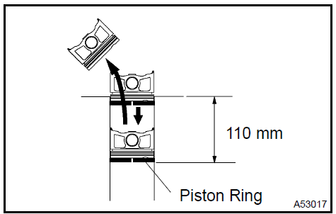
b. Using a feeler gauge, measure the end gap.
Specified end gap:
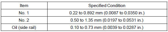
If the end gap is greater than the maximum, replace the piston ring. If the end gap is greater than the maximum even with a new piston ring, replace the cylinder block.
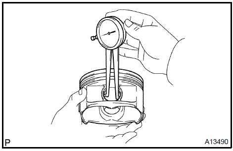
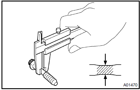
22. INSPECT PISTON PIN OIL CLEARANCE
a. Using a caliper gauge, measure the pin hole bush diameter of the piston.
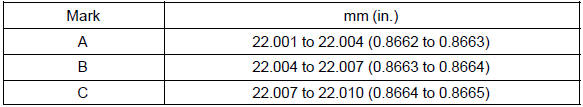
Pin hole diameter: 22.001 to 22.010 mm (0.8662 to 0.8665 in.)
Pin hole diameter (Reference):
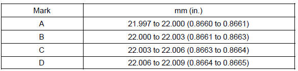
b. Using a micrometer, measure the piston pin diameter.
Piston pin diameter: 21.997 to 22.009 mm (0.8660 to 0.8665 in.)
Piston pin diameter (Reference):
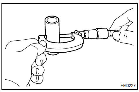
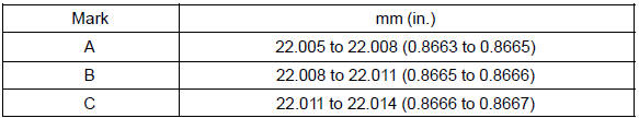
c. Using a caliper gauge, measure the inside diameter of the connecting rod bush.
Bushing inside diameter: 22.005 to 22.014 mm (0.8663 to 0.8667 in.)
Bushing inside diameter:
d. Subtract the piston pin diameter measurement from the piton pin hole diameter measurement.
Specified oil clearance: 0.001 to 0.010 mm (0.00004 to 0.00039 in.)
If the oil clearance is greater than the maximum, replace the connecting rod. If necessary, replace the piston and piston pin as a set.
e. Subtract the piston pin diameter measurement from the bushing inside diameter measurement.
Specified oil clearance: 0.005 to 0.100 mm (0.0002 to 0.0020 in.)
If the oil clearance is greater than the maximum, replace the connecting rod. If necessary, replace the connecting rod and piston pin as a set.
23. INSPECT CONNECTING ROD SUB−ASSY
a. Using a rod aligner and feeler gauge, check the connecting rod alignment.
1. Check for out−of−alignment.
Maximum out−of−alignment: 0.05 mm (0.0020 in.) per 100 mm (3.94 in.)
If the out−of−alignment is greater than the maximum, replace the connecting rod assembly.
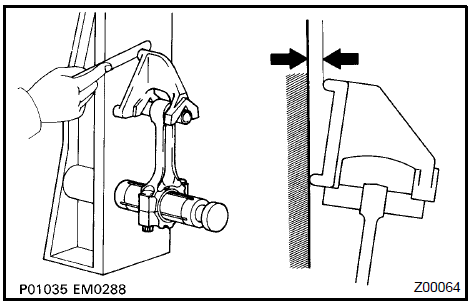
2. Check for twist.
Maximum twist: 0.15 mm (0.0059 in.) per 100 mm (3.94 in.)
If the twist is greater than the maximum, replace the connecting rod assembly.
24. INSPECT CONNECTING ROD BOLT
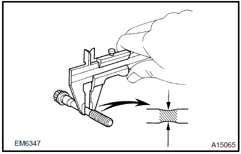
a. Using a vernier caliper, measure the tension portion diameter of the bolt.
Specified diameter: 7.0 to 7.3 mm (0.276 to 0.287 in.)
If the diameter is less than the minimum, replace the bolt.
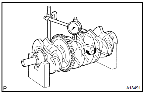
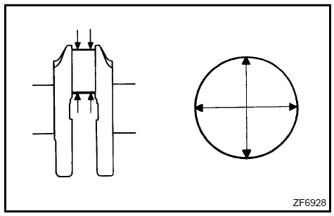
25. INSPECT CRANKSHAFT
a. Using a dial indicator and V−blocks, measure the circle runout, as shown in the illustration.
Maximum circle runout: 0.03 mm (0.0012 in.)
If the circle runout is greater than the maximum, replace the crankshaft.
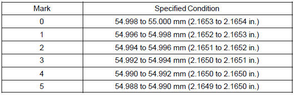
b. Using a micrometer, measure the diameter of each main journal.
Diameter: 54.988 to 55.000 (2.1648 to 2.06535 in.)
If the diameter is not as specified, check the oil clearance (see step 9). If necessary, replace the crankshaft.
c. Check each main journal for taper and out−of−round as shown in the illustration.
Maximum taper and out−of−round: 0.003 mm (0.0001 in.)
If the taper and out−of−round is greater than the maximum, replace the crankshaft.
Diameter (Reference):
d. Using a micrometer, measure the diameter of each crank pin.
Diameter: 47.990 to 48.000 mm (1.8894 to 1.8898 in.)
If the diameter is not as specified, check the oil clearance (see step 2). If necessary, replace the crankshaft.
e. Check each crank pin for taper and out−of−round as shown in the illustration.
Maximum taper and out−of−round: 0.003 mm (0.0001 in.)
If the taper and out−of−round is greater than the maximum, replace the crankshaft.
26. INSPECT CRANKSHAFT BEARING CAP SET BOLT
a. Using a vernier caliper, measure the tension portion diameter of the bolt.
Specified diameter: 7.2 to 7.6 mm (0.283 to 0.299 in.)
If the diameter is less than the minimum, replace the bolt.
Inspect crankshaft bearing cap set bolt
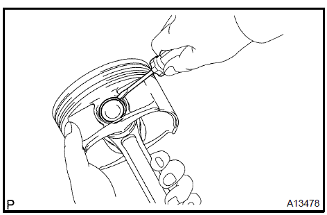
27. INSTALL RING PIN
a. Using a plastic−faced hammer, tap into the ring pin.
 Install ring pin
28. INSTALL TIGHT PLUG
-
Apply adhesive around the tight plugs.
Adhesive: Part No. 08833−00070, THREE BOND 1324 or equivalent.
-
Using SST, install new tight plugs as shown in the illustration.
SST 09950−60010 (09951−00200), 09950−70010 (09951−07100)
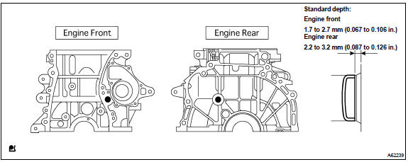 Install tight plug
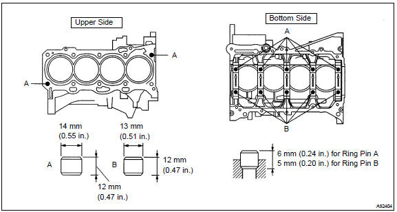
29. INSTALL STUD BOLT
a. Install the stud bolts as shown in the illustration.
Torque:
5.0 N·m (51 kgf·cm, 44 in.·lbf) for stud bolt A
10 N·m (97 kgf·cm, 7 ft·lbf) for stud bolt B
5.0 N·m (51 kgf·cm, 44 in.·lbf) for stud bolt C
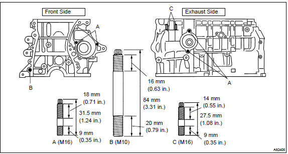 Install stud bolt
30. INSTALL STRAIGHT PIN
a. Using a plastic−faced hammer, tap into the straight pin.
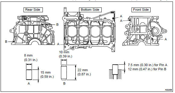 Install straight pin
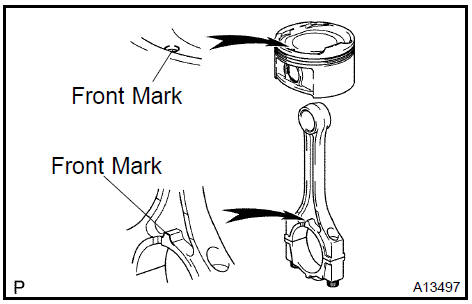
31. INSTALL PISTON
-
Using a small screwdriver, install a new snap ring at one end of the piston pin hole.
-
Gradually heat the piston to approxinately 80 to 90 C (176 to 194 F).
-
Align the front marks of the piston and connecting rod, and push in the piston with your thumb.
-
Using a small screwdriver, install a new snap ring on the other end of the piston pin hole.
32. INSTALL PISTON RING SET
-
Install the oil ring expander and 2 side rails by hand.
-
Using a piston ring expander, install the 2 compression rings with the painted mark as shown in the illustration.
NOTICE: Install the compression ring No. 2 with the code mark (2N) facing upward.
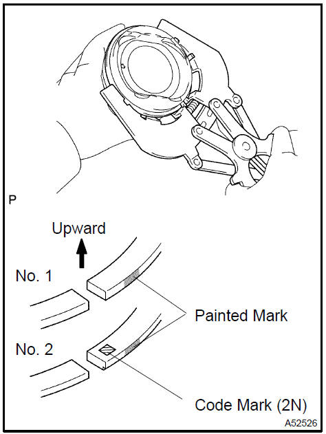
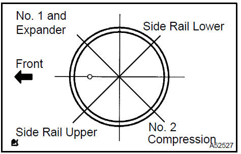
c. Position the piston rings so that the ring ends are as shown in the illustration.
33. INSTALL CRANKSHAFT BEARING
a. Install the upper bearing with an oil groove on the cylinder block.
NOTICE: Clean the backside of the bearing and the bearing surface of the cylinder block and let not stick the oils and fats.
Install crankshaft bearing
34. INSTALL CRANKSHAFT BEARING No.2
a. Install the lower bearing on bearing cap.
NOTICE: Clean the backside of the bearing and the bearing surface of the connecting rod. The surface should be free of dust and oils.
Install crankshaft bearing No.2
35. INSTALL CRANKSHAFT THRUST WASHER UPPER
a. Install the 2 thrust washers under the No. 3 journal position of the cylinder block with the oil grooves facing outward.
Install crankshaft thrust washer upper
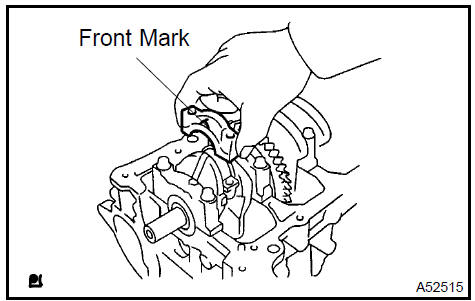
36. INSTALL CRANKSHAFT
-
Apply engine oil to upper bearing and install the crankshaft on the cylinder block.
-
Apply engine oil to the lower bearing.
-
Examine the front marks and install the bearing caps on the cylinder block.
-
Apply a light coat of engine oil on the threads and under the bearing cap bolts.
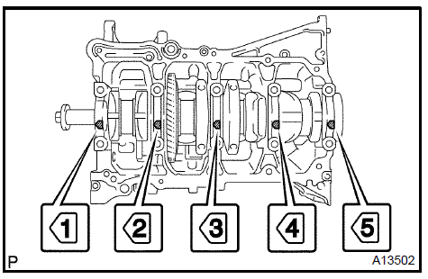
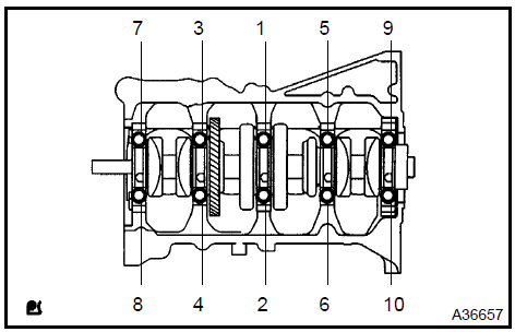
e. Uniformly install and tighten the 16 main bearing cap bolts in the sequence shown in the illustration.
Torque: 20 N·m (204 kgf·cm, 15 ft·lbf)
-
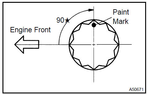
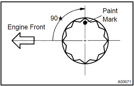
Mark the front of the bearing cap bolts with paint.
-
Retighten the bearing cap bolts by 90 in the numerical order shown in the illustration.
-
Check that the painted mark is now at a 90 angle to the front.
-
Check that the crankshaft turns smoothly.
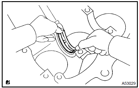
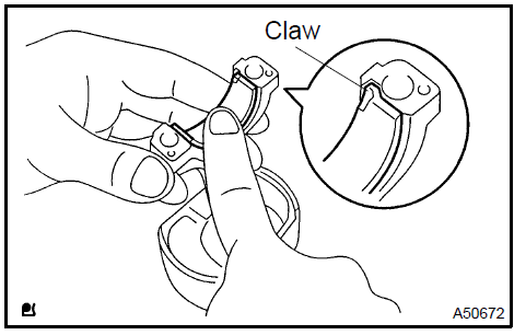
37. INSTALL CONNECTING ROD BEARING
a. Align the bearing claw with the groove of the connecting rod or connecting cap.
NOTICE: Clean the backside of the bearing and the bearing surface of the connecting rod. The surface should be free of dust and oil.
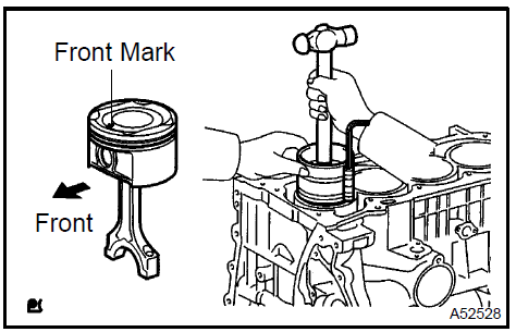
38. INSTALL PISTON
NOTICE: The connecting rod cap bolts are tightened in 2 progressive steps.
-
Apply engine oil to the cylinder walls, the pistons, and the surfaces of connecting rod bearings.
-
Check the position of the piston ring ends.
c. Using a piston ring compressor, push the correctly numbered piston and connecting rod assemblies into each cylinder with the front mark of the piston facing forward.
NOTICE: Match the numbered connecting rod cap with the connecting rod.
-
Check that the protrusion of the connecting rod cap is facing in the correct direction.
-
Apply a light coat of engine oil on the threads and under the heads of the connecting rod cap bolts.
-
Using a 12 mm socket wrench, uniformly tighten the 2 bolts.
Torque: 25 N·m (250 kgf·cm, 18 ft·lbf)
-
Mark the front of the connecting cap bolts with paint.
-
Retighten the cap bolts by 90 as shown in the illustration.
-
Check that the crankshaft turns smoothly.
Engine (2AZ−FE) (From July, 2003)
Timing gear case or timing chain case oil seal (2AZ−FE)(From July, 2003)
Engine rear oil seal (2AZ−FE)(From July, 2003)
Cylinder head assy (2AZ−FE) (From July, 2003)
Cylinder block assy (2AZ−FE)(From July, 2003)
Engine (1MZ−FE/3MZ−FE)
Drive belt (1MZ−FE/3MZ−FE)
Valve clearance (1MZ−FE/3MZ−FE)
Partial engine assy (1MZ−FE/3MZ−FE)
Partial engine assy (2AZ−FE)(From July, 2003)
Partial engine assy (1MZ−FE/3MZ−FE)
Timing belt (1MZ−FE/3MZ−FE)
Camshaft (RH BANK) (1MZ−FE/3MZ−FE)
Camshaft (LH BANK) (1MZ−FE/3MZ−FE)
Cylinder head gasket (1MZ−FE/3MZ−FE)
Cylinder head gasket No.2 (1MZ−FE/3MZ−FE)
Oil pump seal (1MZ−FE/3MZ−FE)
Engine rear oil seal (1MZ−FE/3MZ−FE)
Cylinder head assy (1MZ−FE/3MZ−FE)
Cylinder block assy (1MZ−FE/3MZ−FE)
Partial engine assy (2AZ−FE)(From July, 2003)
Drive belt (2AZ−FE)(From July, 2003)
Valve clearance (2AZ−FE)
Chain (2AZ−FE)(From July, 2003)
Camshaft (2AZ−FE)(From July, 2003)
Cylinder head gasket (2AZ−FE)(From July, 2003)
Toyota Camry XV30 (2002–2006) Service Manual
- Introduction
- Audio & visual system
- Automatic transmission / trans
- Brake
- Clutch
- Communication system
- Cooling
- Cruise control
- Drive shaft / propeller shaft
- Emission control
- Engine control system
- Engine hood/door
- Engine mechanical
- Exhaust
- Exterior/interior trim
- Front suspension
- Fuel
- Heater & air conditioner
- Ignition
- Instrument panel/meter
- Intake
- Lighting
- Lubrication
- Manual transmission/transaxle
- Parking brake
- Power steering
- Rear suspension
- Seat
- Service specifications
- Sliding roof/convertible
- Starting & charging
- Steering column
- Supplemental restraint system
- Theft deterrent & door lock
- Tire & wheel
- Windshield/windowglass/mirror
- Wiper & washer
- Wiring
Categories
